One of the main challenges for performing an EM risk analysis is to identify and mitigate all significant EM threats to a system/item/equipment. Reliance on EMC standards is not sufficient for this, as the EMI threats are evolving more rapidly.
Being an ESR within the PETER project
I started doing my PhD on 11.11.19, as a part of MSCA ITN PETER project (ESR 3), along with 14 other early stage researchers (ESRs). We ESRs (see 12/15 of us, in Figure 1), are currently located in 5 different countries (UK, France, Belgium, Netherlands and Germany) and are working towards developing a “risk-based approach” to EMI (electromagnetic interference) management in various industries (like automotive, medical, defence, marine etc.). My topic in specific is “risk based automotive electromagnetic engineering approach aligned with the ISO 26262 functional safety”. I carry out my PhD research being an automotive electronic research engineer at Horiba Mira ltd., a company which provides automotive engineering consultancy in UK.

Figure 1: (Left) First Network Wide Event (kick-off meeting), Belgium. (Right) Myself and Arun (ESR 9) on top of the Tower Bridge (during our trip to apply for a visa to attend the kick-off meeting in Belgium).
Understanding the concept of risk with an example of COVID-19
Let me use the situation of Betty (35 years), an imaginary person, who gets an invitation (1 among 10 people invited) for a wedding next month. She decides to perform a risk analysis to decide if or not she should attend the wedding during the current pandemic situation.
Not sure of the exact meaning of risk she searches for the definition of risk. A quick Wikipedia search on risk gives her a definition, that reads,
Risk is the potential for uncontrolled loss of something of value. (definition 1)
She was not convinced. Nevertheless, she finds many more definitions of risk, one of which was widely accepted among the scientific community, as also available in many standards, that reads,
Given a hazardous situation, risk is a combination of the probability of occurrence of harm/loss/damage and the severity of that harm/loss/damage. (definition 2)
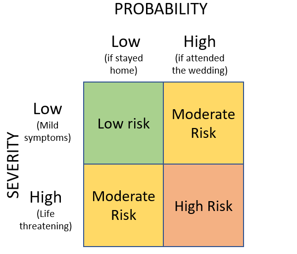
Using definition 2 of risk, Betty drew up a risk matrix as shown in Figure 2.

Figure 2: Risk Matrix for Covid-19.
With the risk matrix and from the news that most of the people who were suffering with life threatening symptoms due to the virus generally had some underlying conditions, Betty (with a long-standing lung problem) figured out that she would be at high risk if she attends this wedding. Hence, she decides not to go and instead sent a request to enable her virtual presence for the ceremony.
The risk matrix derived in Figure 2 is completely qualitative, i.e. guide words like high, low, moderate were used to classify severity, probability and associated risk. A more comprehensive risk analysis to have higher degree of confidence needs to be done quantitatively whenever possible. For example, a quantitative risk analysis can be performed with, the probability of occurrence (derived using statistical data) and/or the severity specified in terms of fixed numbers (like amount of money that will be lost due to the hazard) is available. There are several websites that provide the statistical data (by age, country, no. of cases etc.) for one to determine the risk to a person due to this infection.
However, this is not the same when it comes to risk of malfunction to a safety related system due to electromagnetic disturbances (EMD). Unlike the virus, electromagnetic fields occur in infinite number of different frequencies, amplitudes and modulations, making it economically and technically much more difficult to determine the measures to mitigate all foreseeable and unforeseeable EM interferences (intended and unintended) with safety-related electrical and electronic systems.
Need for electromagnetic risk analysis for functional safety
Currently, to ensure functional safety, the automotive industry employs ISO 26262 [1], a functional safety standard developed specifically for road vehicles. This standard includes a risk-based approach to establish an automotive safety integrity level (ASIL). The ASIL value (ranging from A to D, with D being the highest and A is the lowest) is an attribute of the safety goal and its associated safety requirements that describes the rigor of the engineering of the safety mechanisms and mitigation measures implemented to mitigate the risk of failure for an item that performs a safety related function.
Although EMI is a potential cause of systematic system failures, the failure rates available from the commonly recognised industry sources (e.g. Siemens SN 29500 document [2] ), mostly fail to consider possible EMI aspects. There are some standards and guides [3, 4, 5], which specify relevant EMD found in typical operational environments like residential, industrial and commercial (based on measurements, previous experience and technical judgement), as well as mitigation measures for functional safety against EM threats. They are referred to, when testing an equipment for immunity against EMD.
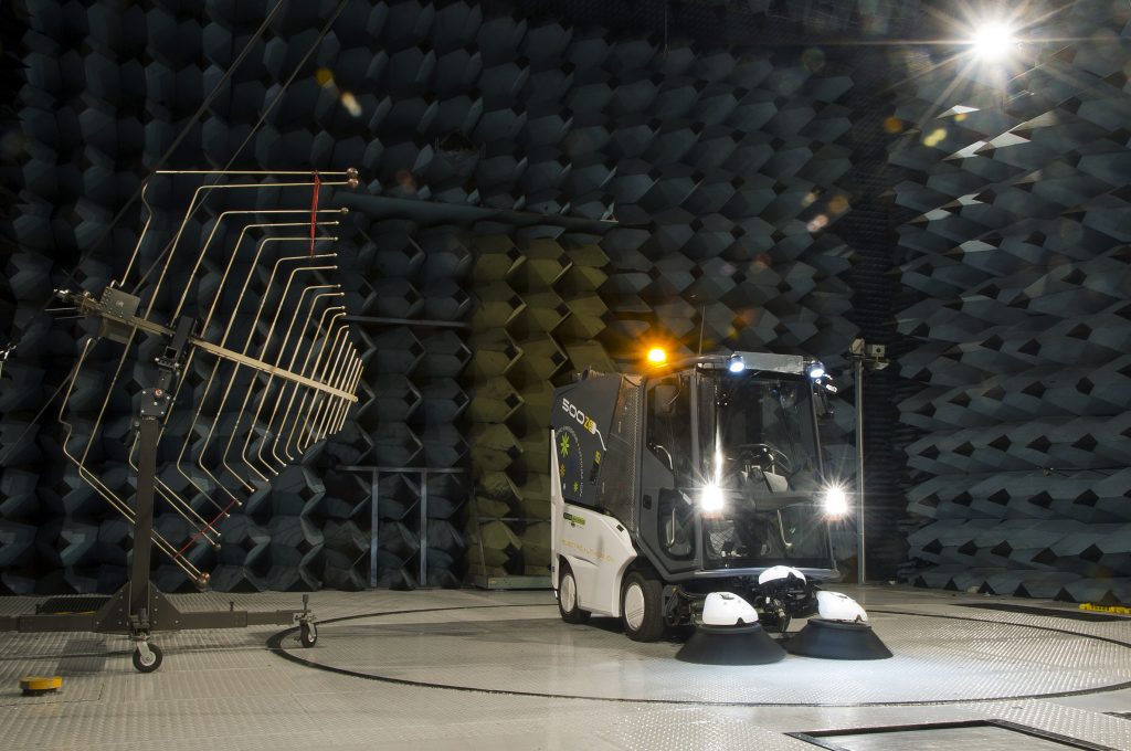
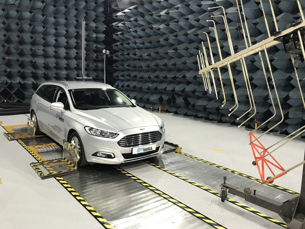
Independently of functional safety, validation of the vehicle performance and design verification of its elements is carried out for electromagnetic compatibility (EMC) purposes. This is done through immunity and emission tests at vehicle and subsystem level, in order to gain confidence that the vehicle will be able to operate in, and not further degrade, the operational electromagnetic environment. Legislative requirements for these tests are detailed in [6], for the European market, although most vehicle manufacturers choose to apply more stringent limits in order to ensure robustness and customer satisfaction. Nonetheless, tests performed within controlled EM environments such as open area test sites (OATS, see Figure 3), semi-anechoic chambers (see Figure 4–Figure 6) and reverberation chambers cannot fully reflect the actual operational electromagnetic environment of the vehicle, or its sub-systems. In addition, standard EMC tests are not completely adequate to ensure safety from EMD [7].

Figure 3: An earth mover undergoing radiated emissions testing on the HORIBA-MIRA OATS.

Figure 4: EMC immunity test of a street sweeper inside a semi-anechoic chamber at HORIBA MIRA.

Figure 5: EMC testing of a helicopter in a semi-anechoic chamber at HORIBA MIRA.

Figure 6: EMC radiated immunity testing of a car on a dynamometer in a semi-anechoic chamber at HORIBA MIRA.
Inputs for System level EM risk analysis for functional safety:
An assumption of a hazardous situation is one of the prerequisites to perform a risk analysis. As demonstrated with an example in Section III, the probability of occurrence and the severity of harm associated with the hazardous situations are also essential attributes that are required to estimate the associated risk. In EM risk analysis for functional safety, the probability of malfunction due to EMI and the severity of the consequence due to that malfunction can be used. For a given safety-related item, performing a hazard and risk analysis as described in the concept phase of ISO 26262, can provide valuable inputs to help in the development of an EM risk analysis model, such as:
- system architecture
- safety-related malfunctions
- possible hazardous situations
- ASIL values (derived using exposure, severity and controllability values associated with a hazardous situation
- functional safety requirements
- dependability failure analysis (to identify common-cause and cascaded failures), etc.
These inputs, and results from fault tree analysis, event tree analysis and failure mode and effect analysis that are generally used in functional safety analysis, can also be reused to support an EM risk analysis. A proposed method which can be used to perform an EM risk analysis is given in steps below:
- Obtain the system architecture to enable system visualization using graphical networks (nodes and edges).
- Based on the coupling (wired and wireless) of various elements (nodes in the graphical network) and their functional dependencies, nodes are connected by edges.
- Determining the spatial location of each element in the system, if possible.
- Distinguish the functions as safety and non-safety functions.
- Assigning the elements with immunity levels to be tested and emission levels expected.
- Identify the elements and functions, which are more likely to compromise systems safety when being interfered with EMD.
- Evaluate and determine the safety measures and EMC test levels.
As mentioned before, one of the main challenges for performing an EM risk analysis is to identify and mitigate all significant EM threats to a system/item/equipment. Reliance on automotive EMC standards is not sufficient for this, as the EMI threats are evolving more rapidly with the deployment of new technology and standards struggle to keep pace with the rate of change. Hence, a comprehensive EM risk analysis, as proposed above, is desirable for manufacturers to demonstrate due diligence in the management of possible risks in the development of their products.
REFERENCES
[1] BS ISO 26262:2018, “Road vehicles — Functional safety”, 12 parts, December, 2018.
[2] SN 29500:2013, “Failure rates of components”, Siemens Standard, Revision 2013-07.
[3] BS EN 61326-3-1:2017, “Electrical equipment for measurement, control and laboratory use. EMC requirements – Part 3-1: Immunity requirements for safety-related systems and for equipment intended to perform safety-related functions (functional safety) – General industrial applications”, British Standards Institute, February 2017.
[4] BS EN 61000-2-5:2017, “Electromagnetic compatibility (EMC). Environment. Description and classification of electromagnetic environments”, British Standards Institute, February 2017
[5] IET, “Guide on EMC for Functional Safety”, 2008. Online: www.theiet.org/factfiles/emc/emc-factfile.cfm .
[6] UNECE Reg10:2012, “Regulation No. 10 – Uniform provisions concerning the approval of vehicles with regard to electromagnetic compatibility”, Add. 9, Rev. 4, 06/03/2012
[7] K. Armstrong, “Why EMC testing is inadequate for Functional Safety – and what should be done instead,” 1st IET International Conference on System Safety, Savoy Place, London, UK, 2006, pp. 179-183.
About the Author: Lokesh Devaraj
 Lokesh Devaraj is currently living in a small town of UK called Nuneaton. He comes from a city called Chennai, located along the south east coast of India (population fact: Austria, a country around 200 times larger than Chennai by area, has only 84% of Chennai’s population!). He obtained his Master’s degree in Advanced Optical Technologies at Friedrich–Alexander University Erlangen–Nürnberg. Besides academics, he was also involved in performing optical computations and laboratory experiments at various research institutes namely Fraunhofer IISB, ASML and AOTTP. In year 2017, Lokesh completed his Bachelor’s degree in the major Electronics and Communication Engineering at RMKCET, Tamil Nadu, India.


