
RMCD: a potential but easily overlooked culprit of EMI and EMI-related risks
I. EMI and its Management
With more and more industries in the world being “conquered” by all kinds of electronic devices/systems, the safety of electronic devices/systems is a growing concern. One way that electronic devices/systems may cause safety issues is by electromagnetic interference (EMI). It has been widely reported that EMI can cause not only emission issues, but also immunity issues. To prevent (or a least reduce) the influences of this unintended EMI, a “rule-based” approach has been adopted for a long time [1][2]. In recent years, to better manage the influences of these unintended EMI issues, a “risk-based” approach has been proposed and is now being more and more widely adopted [2], on top of the “rule-based” approach. Electromagnetic compatibility (EMC) is used to describe the “anti-EMI” ability of a device/system from the perspectives of both emission and immunity. Once the consequences caused by EMI of a device/system are not critical (i.e., the safety level regarding EMI of a device/system is considered to be acceptable, based on “rule-based” and/or “risk-based” approach), the device/system is regarded as EMC-compliant.
However, even if both the “rule-based” and the “risk-based” approach are adopted, achieving EMC compliance for a complicated system (e.g., a composite system composed of multiple devices, such as an operation room of a hospital which consists of many electronic medical devices) still requires great care. This is due to firstly the limitations in the published testing standards [3], and secondly to possible insufficient consideration during the risk management process. For example, for the “rule-based” approach, current adopted EMI testing standards mainly focus on active devices [4], thus the influences of passive devices are not well considered during the EMC tests; for the “risk-based” approach, if the influences of passive devices in certain environment can’t be sufficiently recognized, some potential risks could also be overlooked during the risk analysis process. In the following content, based on observations of a real-life example, simulations have been done to show that the passive components can indeed significantly contribute to EMI issues and should be well managed before the whole system is put into application.
II. RMCD in Hospital lead to Dangerous Situation
In real life, there are already some reported cases that passive components can cause EMI issues. One such example relates to images on medical displays in an operation room (as shown in Fig. 1) being disturbed by the nearby use of an electrosurgical knife [5]. In this case, it was observed that once the electrosurgical knife was in operation, the images collected by the endoscope and shown on the medical display were disturbed. Since the surgery is very much dependent on the accurate image on the medical displays, this disturbance could mislead the surgeon’s judgement and therefore cause catastrophic consequences.
The reason of such disturbances was that the radiated EMI from the electrosurgical knife coupled into the medical display system and interfered with the intended input signals. Although all the displays used in the operation room had already passed the required EMC tests, this coupling effect in the installation was not revealed by the standard EMC tests. Further debugging showed that this coupling effect actually happened via the wall plug (as shown in Fig. 2(a)), a type of passive component known as “ready-made connecting device” (RMCD). RMCD is defined as a set of cables/connectors inside electronic systems for the transmission of data and/or power. As can be seen in Fig. 2(b), in this example, the RMCD (i.e., the wall plug) is not 360° fully shielded. Instead, the RMCD connects the shielding of eight pairs of coaxial cables with only a few grounding (GND) wires. Such imperfect connection created a coupling path for the radiated EMI from the nearby electrosurgical knife and thus caused the image disturbance issues. This example proves that RMCDs could cause EMC-related issues, although they are passive components. Therefore, during the process to achieve EMC-compliance, in addition to active devices/systems, such RMCDs should also be taken into consideration.
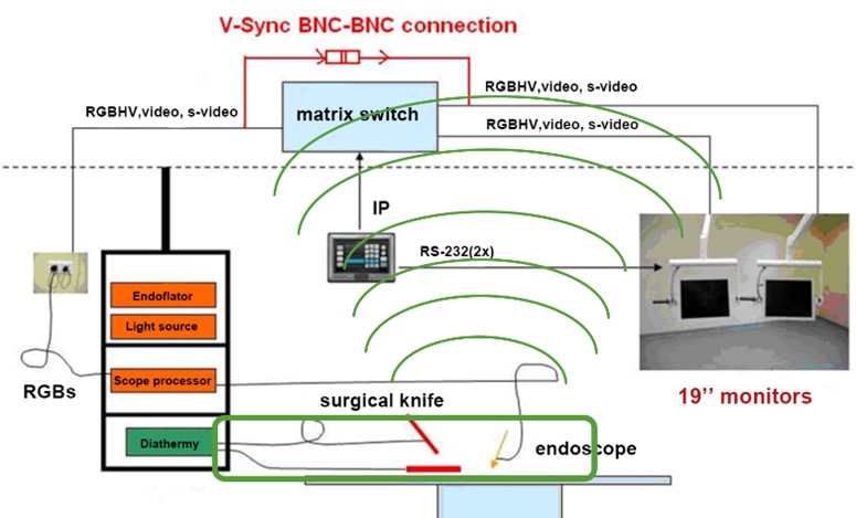
Fig. 1. Conceptual overview of a typical operation room with a surgical knife and medical displays
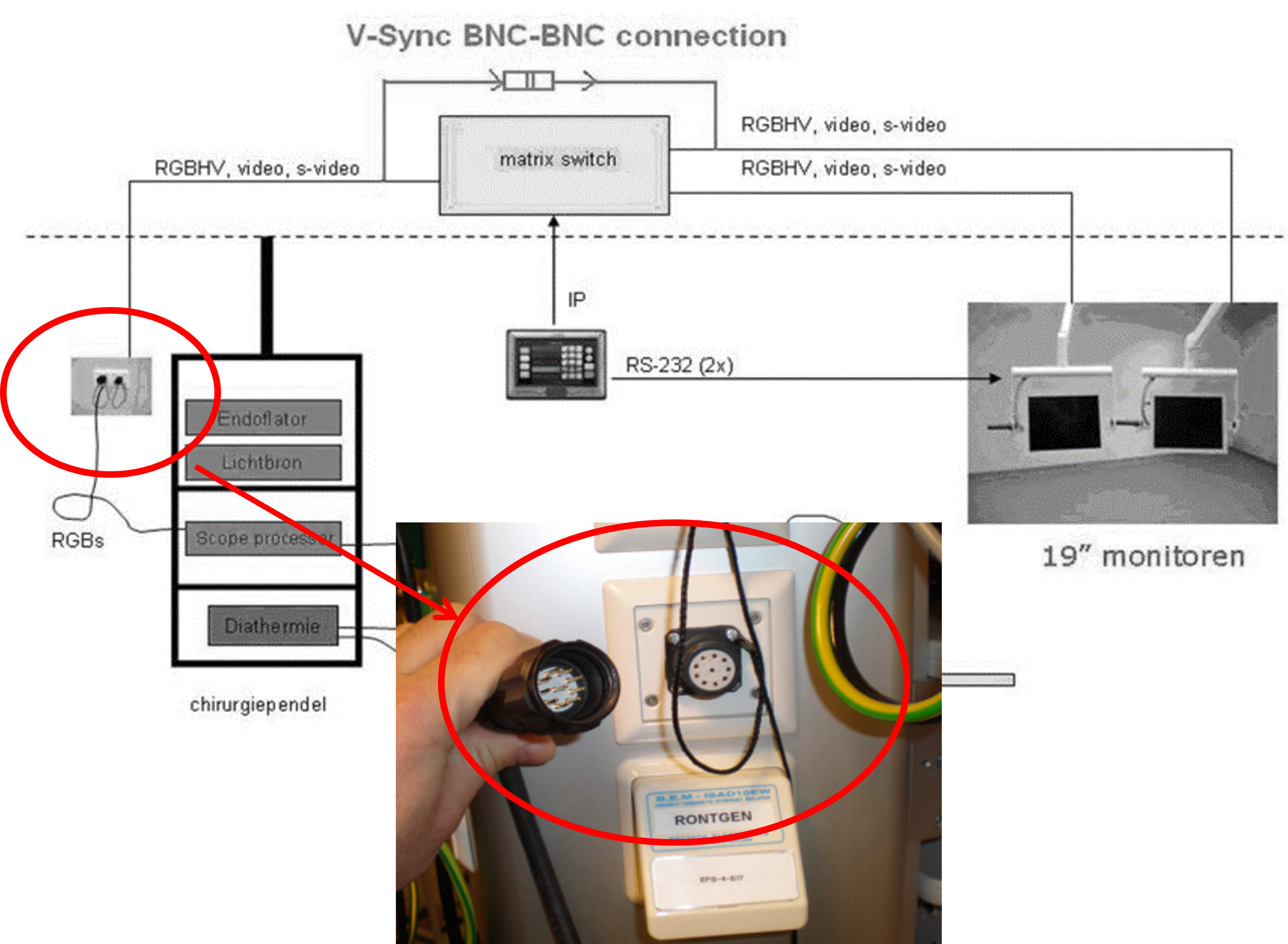
Fig. 2a) Wall plug in the operation room
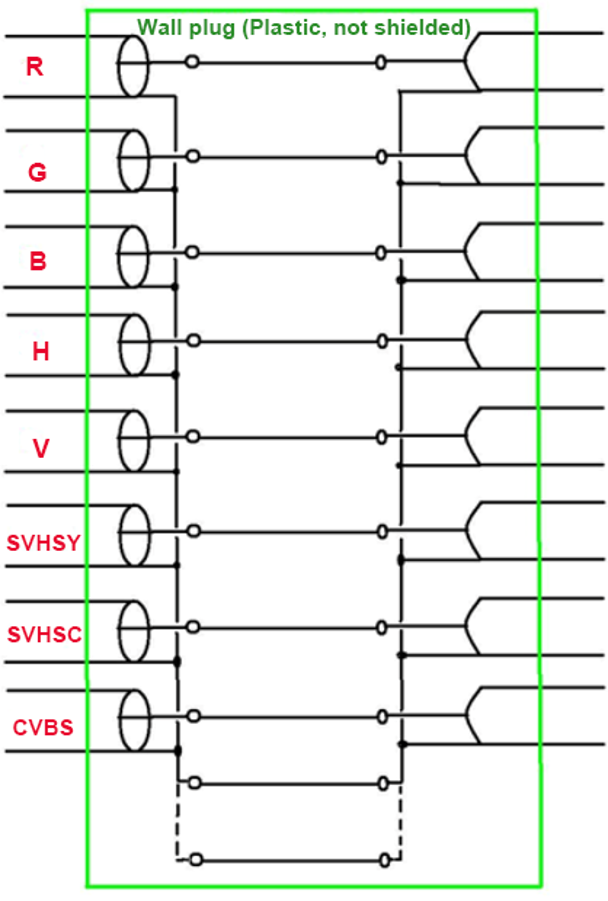
Fig. 2b) Schematic of the wall plug

Fig. 2b) Example of the wall plug (ready-made connector)
III. Investigation of some Characteristics of an RMCD
Based on the above real-life example, we know that RMCDs could influence the EMC of a system, thus it is important to know how the characteristics of RMCDs can play a role. Considering that in real life, RMCDs (more specifically, the connector part of a RMCD) applied in different applications could have different lengths and could be placed in any locations along the cables, the length and location of connectors should be very practical characteristics to investigate. Besides, for not fully shielded RMCDs, different manufacturers could possibly choose a different number of GND wires for cable shielding connection, thus the number of GND wires could also be a good practical characteristic for investigation. Therefore, in the following content, the length, the number of GND wires and the location of RMCDs are chosen to be investigated based on simulations. Corresponding setups and results are described below.
A. Setup
With the full-wave EM simulation tool PathWave EM Design (Keysight Technomphies), as shown in Fig. 3 (a), an RMCD model which contains two coaxial cables (with 50 Ohm characteristic impedance, verified by S11 in Fig. 4) and a “pigtail-like” connector was created. Fig. 3 (b) shows that the coaxial cable model is with a square cross-section (to accommodate the rectangular mesh of the simulation, this should not affect the conclusions as long as the impedance is correctly designed). Fig. 3(c) shows the connector which consists of four conducting GND wires, connecting the shield of the two coaxial cables.
To optimize the simulation, based on the principle of reciprocity, the RMCD is used as an emitter instead of a receiver in the simulations. By observing the total radiated power in the surrounding environment, similar conclusions could be drawn for when the RMCD acts like a receiver. For such a transmitter, a Gaussian pulse with a net available power 2.5 mW was adopted as the input signal and applied at one end of the RMCD (black arrow in Fig. 3(a)). The other end of the RMCD was terminated with a matched passive impedance (red arrow in Fig. 3(a)).
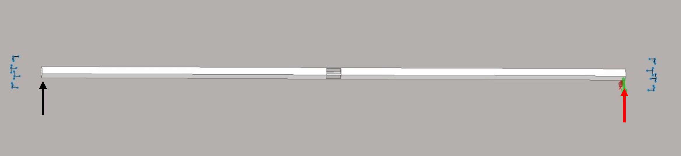
Fig. 3a) Simulation model, overview of RMCD
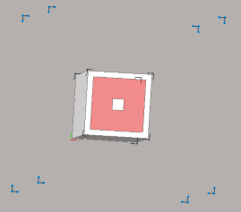
Fig 3.b) Simulation model, cross section of coaxial cable
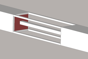
Fig. 3c) Simulation model, pigtail-like connector
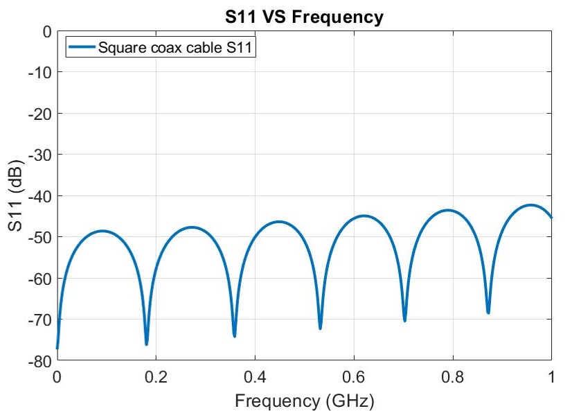
Fig. 4. Verification of the coaxial cable characteristic impedance: frequency domain results (S11)
B. Results
As mentioned above, three characteristics were chosen for investigation. For each characteristic, the corresponding examples and results are individually shown below.
- Length of Connectors
To investigate the influences of the connector length, the connector with 1 GND wire was set to the length of 1 cm, 2 cm and 3 cm, respectively, while the two coaxial cables are both 50 cm (i.e., the connector was always at the center of the RMCD), as shown in Fig. 5(a). The total radiated power of each length is shown in Fig. 5(b). From the figure, it can be concluded that longer connectors can lead to higher radiation. This is because a longer connector leads to a higher impedance shielding connection between the two coaxial cables. With the same amount of return current flowing through the GND wiring, the higher impedance connection results in a higher coupling voltage and thus more EMI can be radiated or picked up.
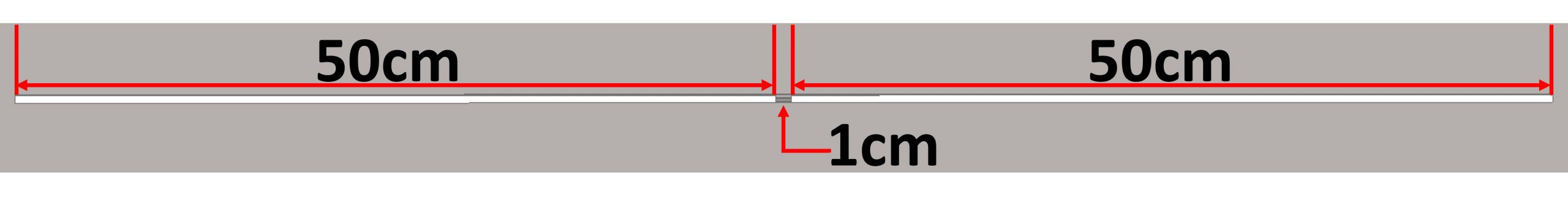
Fig. 5a) Investigation of influences of connector length, 1cm example
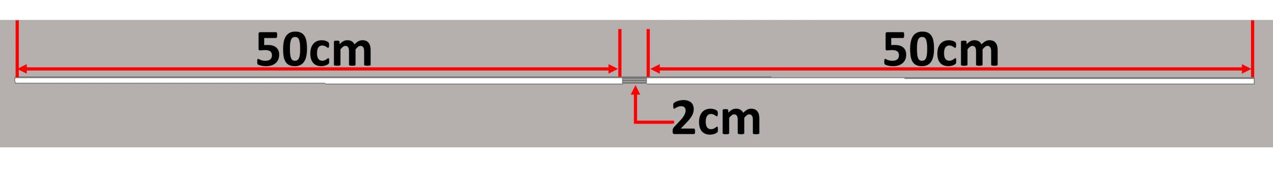
Fig. 5a) Investigation of influences of connector length, 2cm example
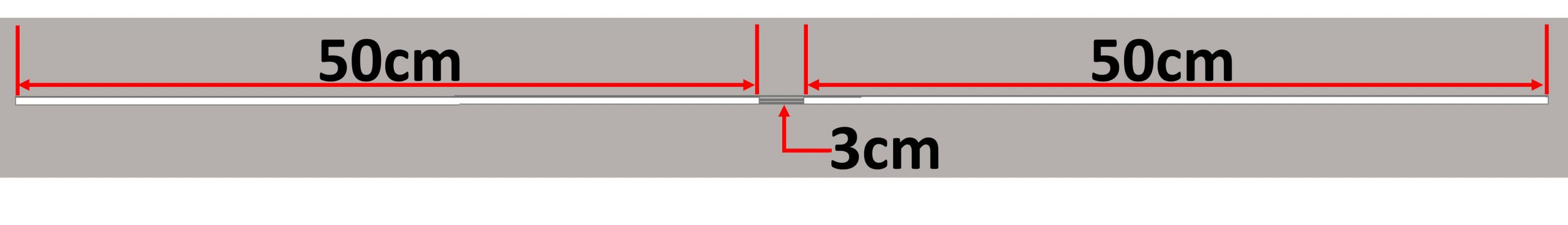
Fig. 5a) Investigation of influences of connector length, 3cm example
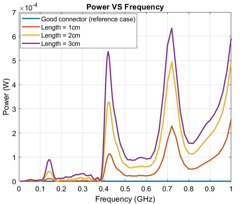
Fig. 5b) Investigation of influences of connector length, results
- No. of GND wires of connectors
Then the influence of the number of GND wires of the connector was investigated. The number of the GND wire was set to 1, 2 and 4, respectively, while the connector with a length of 1 cm was again put at the center of the RMCD, as shown in Fig. 6(a). The total radiated power of each case is shown in Fig. 6(b). The results indicated that more GND wires can greatly reduce the radiation. Similar as above, this is due to the decreased impedance of the shielding connection between the two coaxial cables, which is caused by increasing the number of GND connecting wires.
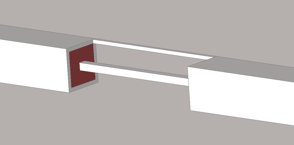
Fig. 6a) Investigation of influences of number of GND wires, 1 wire example
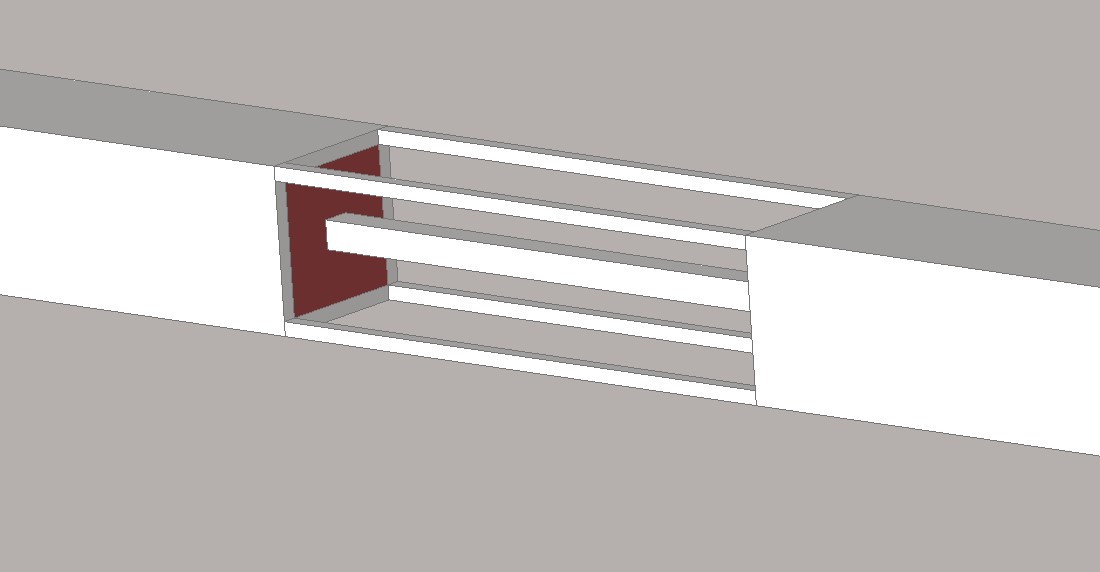
Fig. 6a) Investigation of influences of number of GND wires, 4 wires example
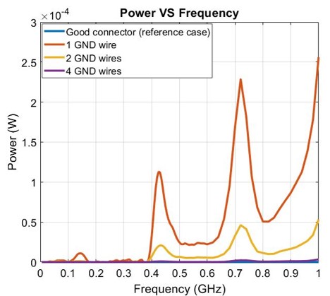
Fig. 6b) Investigation of influences of number of GND wires, results
- Location of Connectors
Finally, the influence of the connector location was explored. In three different cases, the connector was placed at a distance of 20 cm, 25 cm and 50 cm from the source end, respectively, as shown in Fig. 7(a). In each case, the connector was always set to be 1 cm with 1 GND wire. Again, the total radiated power of each location case is compared. From Fig. 7(b), it can be observed that different connector locations lead to almost the same fundamental radiation peak. Besides, when the connector is placed at a symmetrical location (here is the case of 50 cm distance to the source end), only the odd harmonics will be excited, while even harmonics can also be excited when the connector is placed at an asymmetrical location. This behavior is similar to a dipole antenna [6][7].
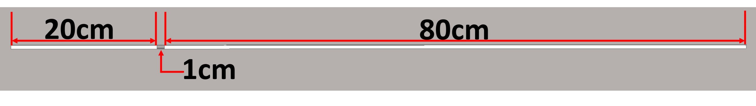
Fig. 7a) Investigation of influences of connector location, 20-80 example
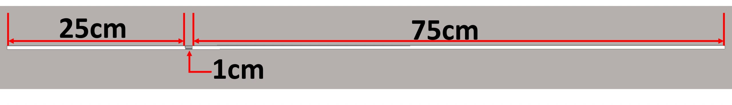
Fig. 7a) Investigation of influences of connector location, 25-75 example
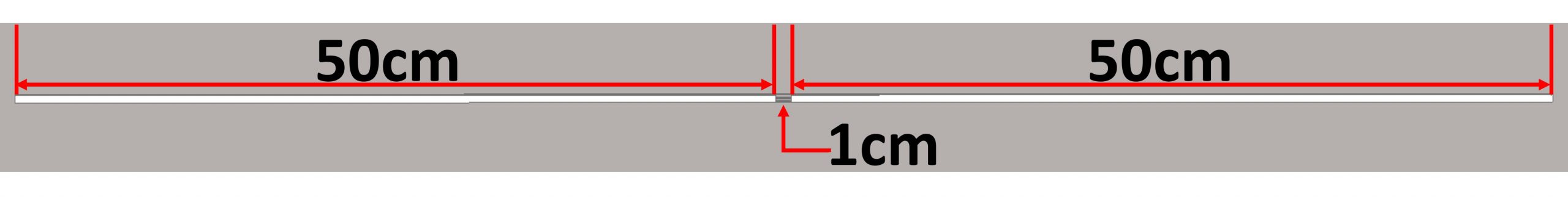
Fig. 7a) Investigation of influences of connector location, 50-50 example
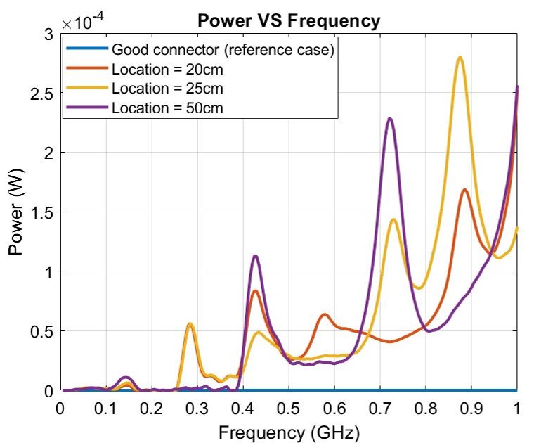
Fig. 7a) Investigation of influences of connector location, results
IV Conclusions
From a real-life example of an operation room, this blog has introduced RMCD and shown that passive components can also lead to EMI issues that are not covered by standard EMC tests. By simulations, the influence of individual characteristic of a RMCD on radiated EMI has been investigated and could provide insights on solving EMI issues. In the future, a more in-depth theoretical analysis could be developed to further explain the influence of RMCD on EMI and more practical methods could accordingly be proposed to improve the EMC of a complex electronic system.
References
[1] F. Leferink, J. van der Ven, H. Bergsma and B. van Leersum, “Risk based EMC for complex systems,” in 2017 XXXIInd General Assembly and Scientific Symposium of the International Union of Radio Science (URSI GASS), Montreal, QC, 2017, pp. 1-4.[2] F. Leferink, “Risk-based vs Rule-based Electromagnetic Compatibility in Large Installations,” in 2018 IEEE 4th Global Electromagnetic Compatibility Conference (GEMCCON), Stellenbosch, South Africa, 2018, pp. 1-4.
[3] K. Armstrong, “Why increasing immunity test levels is not sufficient for high-reliability and critical equipment.” In 2009 IEEE International Symposium on Electromagnetic Compatibility, pp. 30-35.
[4] K. Hemmerlein, R.Damm, B.Mund, M.Kotzev, and T.Schmid. “EMC of Ready-Made Connecting Devices (RMCDs).” International Cable & Connectivity Symposium – Proceedings of the IWCS 2020 Virtual Conference, October 2020.
[5] Z. Chen, J. Catrysse, R. Deseine, T.Claeys, D. Pissoort, “Case Study of Electromagnetic Interference in Surgery Environment”, XXXI International Scientific Conference Electronics-ET2022, September 2022.
[6] P. Lawson, J. Godfrey and A. Lavrenko, “Evaluation of an Off-Centre Fed Dipole Antenna in Passive Harmonic Radar Tags,” 2020 4th Australian Microwave Symposium (AMS), 2020, pp. 1-2, doi: 10.1109/AMS48904.2020.9059370.
[7] N. Ishii, “Analysis on balanced and unbalanced modes for dipole antennas using characteristic modes,” 2014 International Symposium on Antennas and Propagation Conference Proceedings, 2014, pp. 239-240, doi: 10.1109/ISANP.2014.7026619.
About the Author: Zhao Chen
 Zhao Chen is an Early Stage Researcher, affiliated with the Healthcare R&D department at Barco NV. As ESR12, he will focus on EMI-Resilient Medical Display systems for Surgical- and Diagnostic Imaging and Modality Applications. His ultimate objectives are to complete and optimize the existing rule-based Design-for-EMC process with/for IEC 60601-1-2:2014, to specify test-cases that are based on different types and use cases of displays and display systems for medical application and to apply and assess the novel EM-risk analysis methodology on the test-cases.
![]()